And away we go….
Posted By Russ Emerson on March 6, 2010 at 2:41 pm
Going by the manual, the building process for the Launch is broken down into six major stages. The first stage consists of assembly of the keel/stem/sternpost, and construction of the framing jig.
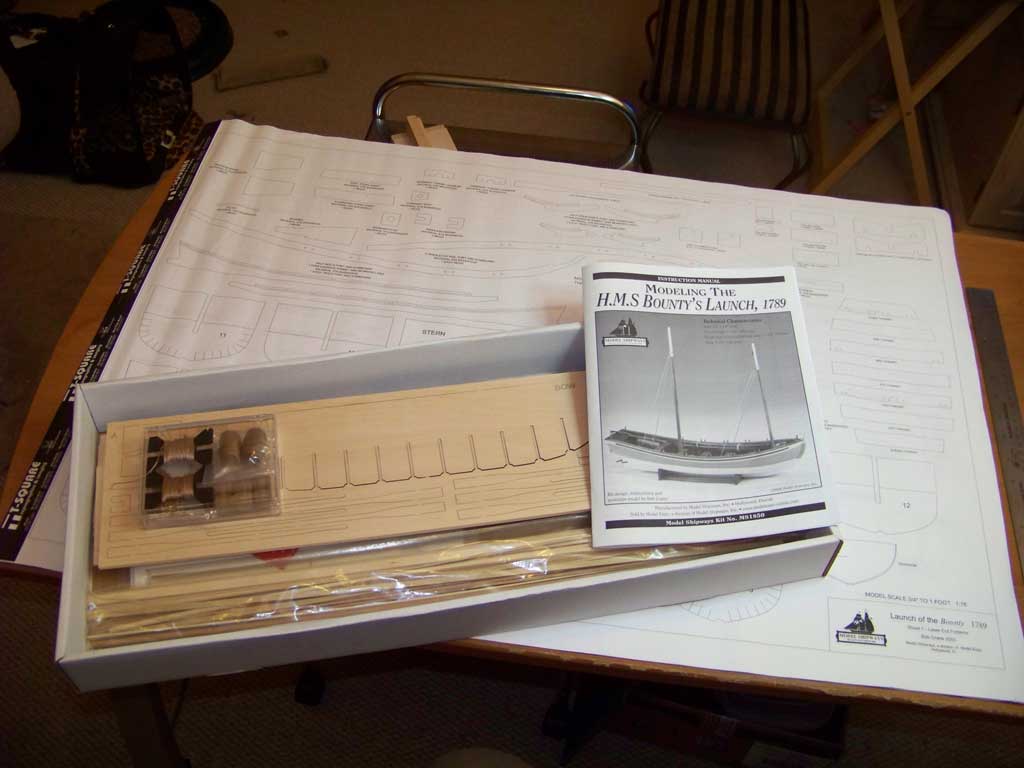
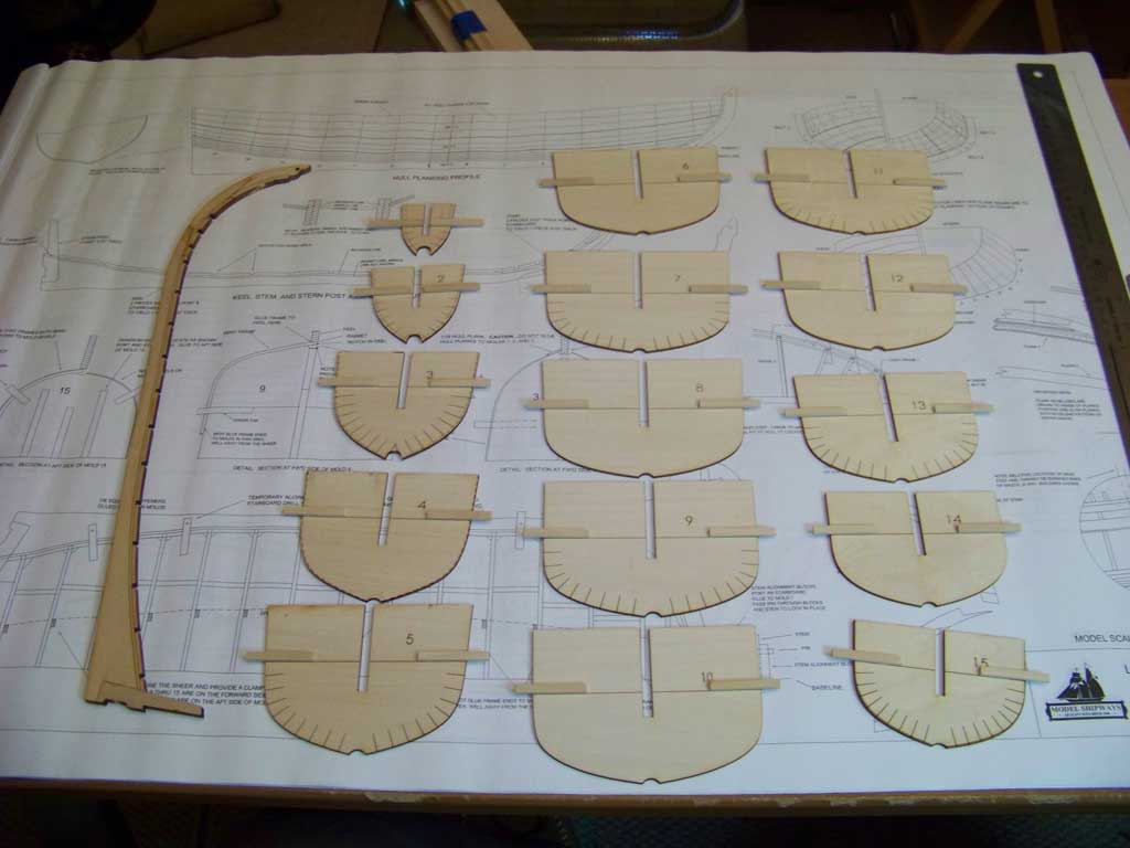
The first thing one does, though, is to ensure that everything that is supposed to be included in a kit is, in fact, included. In this case, the kit contains sheets of laser cut parts, bundles of strip materials, sailcloth, fittings, accessories, sheets of plans and the manual.
[Click to embiggen]
I’d always heard that Model Shipways’ kits included the highest quality woods, and this kit certainly bears that out. The sheets of basswood are straight-grained and free of blemishes. The plywood sheets are also high quality. The laser cutting seems to be as accurate as, well, a laser. The plans are exceptionally well drawn.
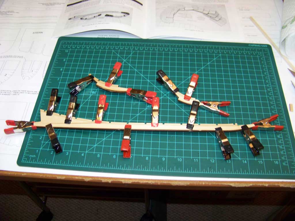
The first step in construction was to assemble the keel and the stem pieces, which are laminated together from pieces of 3/32″ basswood, left and right sides, each of which is marked with lines for the rabbet. I wondered why they didn’t just cut the parts from a single piece of 3/16″ basswood, until it occurred to me that it would be virtually impossible for their manufacturing process to accurately align the rabbet markings on both sides of a single piece of wood — and accuracy is critical.
Did I mention the accuracy of the laser cutting? Holy smokes. The halves of the keel and stem pieces aligned absolutely perfectly.
I used just a few touches of wood glue to tack the parts together, then clamped them. Most of the gluing was then done with cyanoacrylate wicked between the parts; the idea was to avoid the warping that often accompanies the use of water-based glues with wood.
[Click to embiggen]
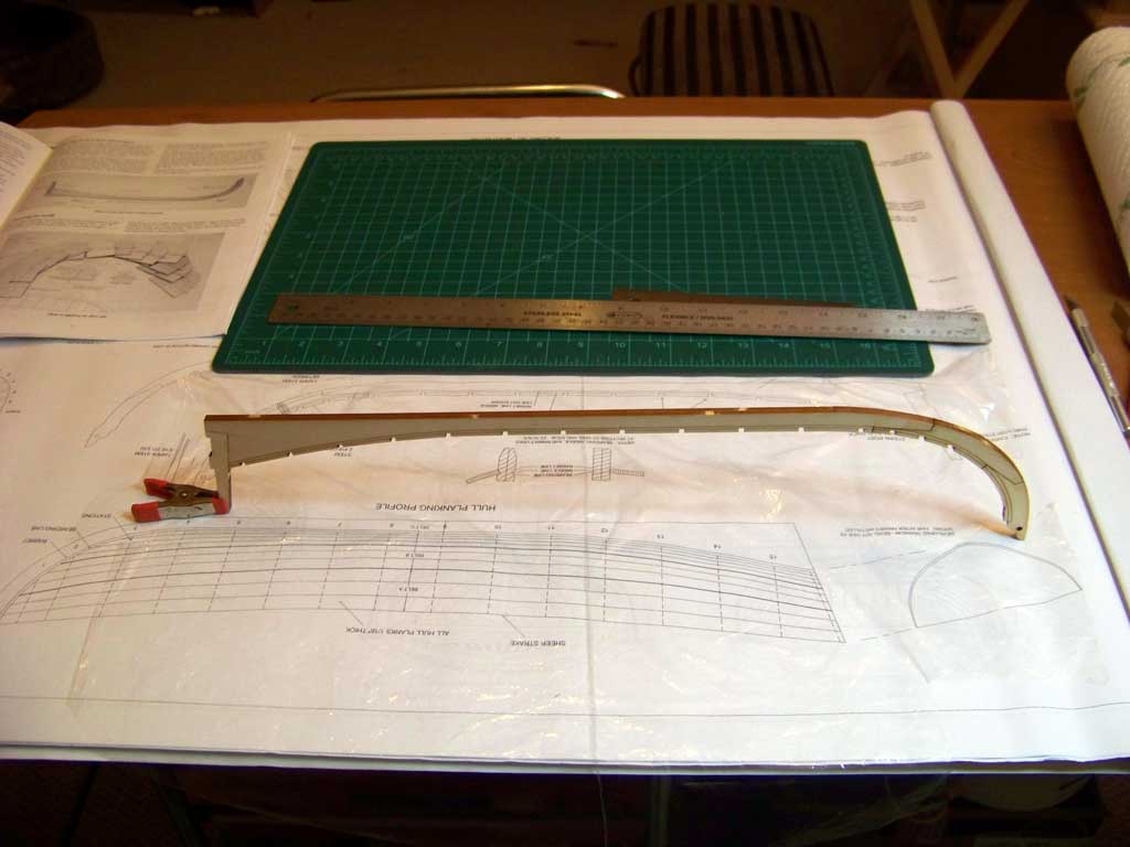
Once the glue had cured, I then assembled the stem pieces to the keel, and added the one-piece sternpost.
[Click to embiggen]
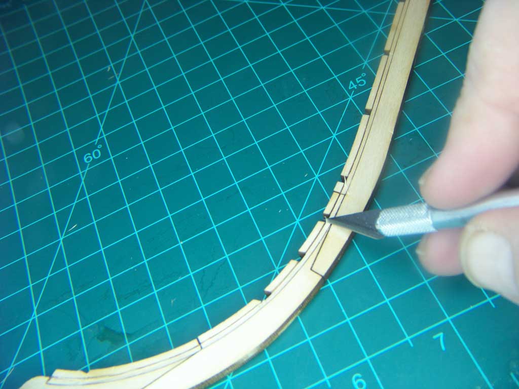
The parts all securely fastened to each other, I then followed the manual’s recommendation, and cut the rabbet, into which the hull planking will later fit, on both sides of the assembly. A brand-new (and exceptionally sharp) X-Acto blade helped to make quick work of the task.
Well, OK, not quick quick — I took my time to get it as right as possible.
[Click to embiggen]
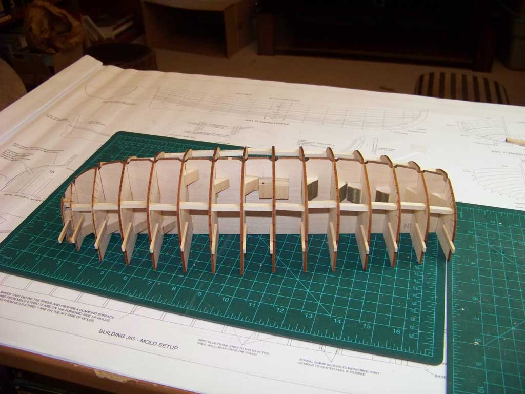
Earlier, while the keel assembly had been curing, I cut out and cleaned up the parts that go together to make the framing jig, then cut some strip basswood to make the sheer line reference tabs, which were glued onto the molds, located by conveniently pre-marked (there’s that laser again) lines.
[Click to embiggen]
Finally at this stage, I assembled and glued the molds to the center “false” keel one at a time, being sure that each was square to the keel. I went a bit beyond the kit instructions and reinforced the joint between each with a block of basswood, and then, per the manual, braced the edges of the molds fore and aft with short lengths of basswood; I used 3/16″ wood out of my own stock rather than the 1/8″ supplied with the kit. Each piece was sawn to approximate length, then sanded to length, to fit between the molds without nudging them out of alignment; friction held them all in place until I used a dab of CA glue to fix them permanently.
[Click to embiggen]
Next up: fairing the molds, and making the frames.
Comments